Automating a Canon camera with an Arduino - Part 2
I did some experimentation today with the control setup I was writing about...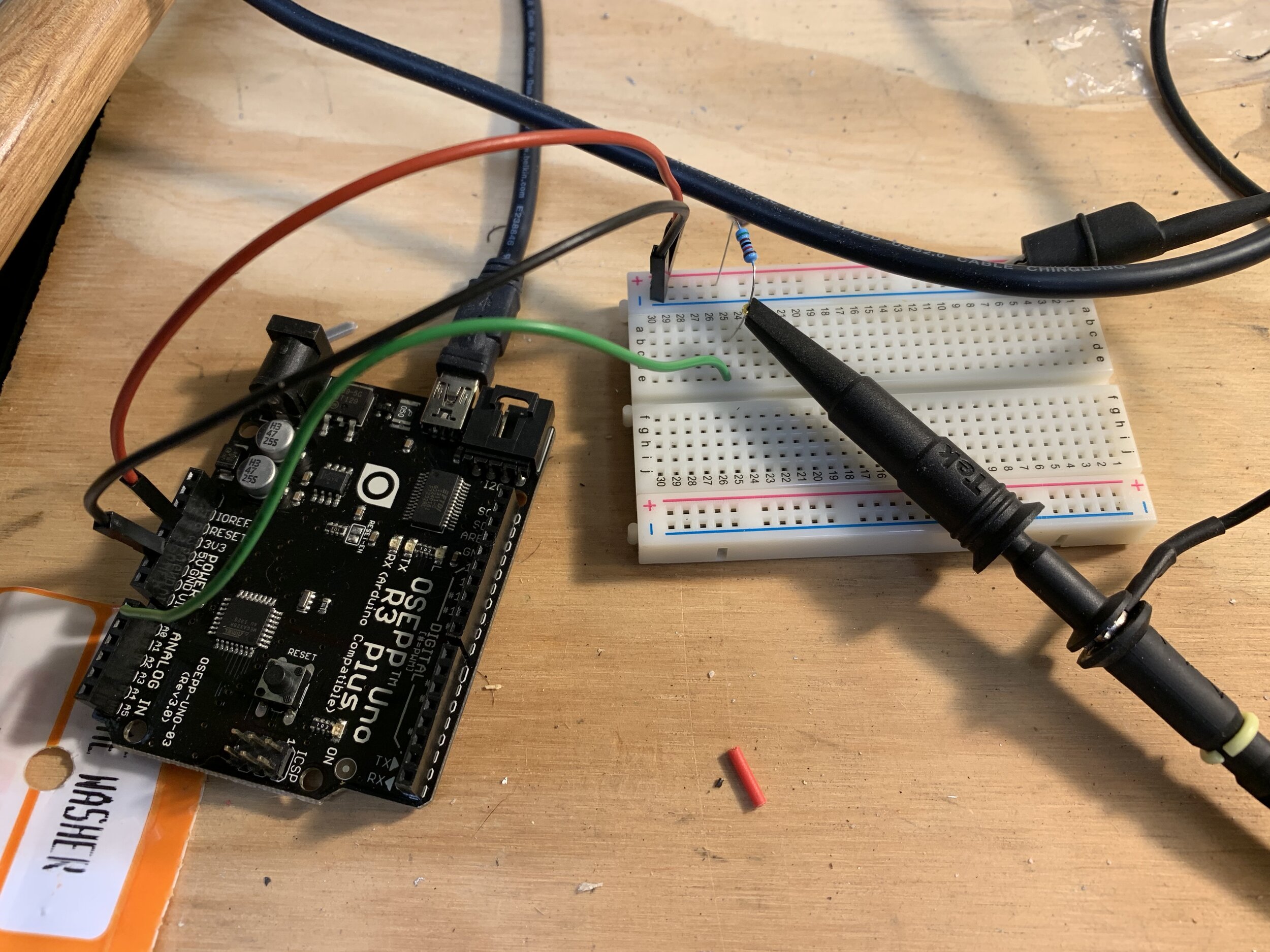 This is a super simple circuit that I didn't even need the breadboard for, but I broke it out because... why not?All that's going on is the power, 3.3V in this case, and ground are being pulled off the Arduino and I have a 51K resistor off the positive rail to serve as a pull-up. Under there, with the green wire, is a connection to the analog 0 (A0) line that can pull that down to ground if I want to.The code is super simple too:
#include#define SHUTTER_PIN A0void setup() {Serial.begin(57600);pinMode(SHUTTER_PIN, INPUT);}void loop() {int readByte;if (Serial.available() > 0) {readByte = Serial.read();if (readByte == 'c') {captureImage();}}}void captureImage() {Serial.print("Shutter -- ");pinMode(SHUTTER_PIN, OUTPUT);digitalWrite(SHUTTER_PIN, 0);delay(100);pinMode(SHUTTER_PIN, INPUT);Serial.print("done\n");}
All that's going on is the Arduino is waiting for a "c" (for capture) to be read from the serial line, then it takes the pin from an input (which is high impedance, or super high resistance) to an output (which is low impedance). When I write a 0 to it, it just pulls it down to ground.And as it looks on the scope...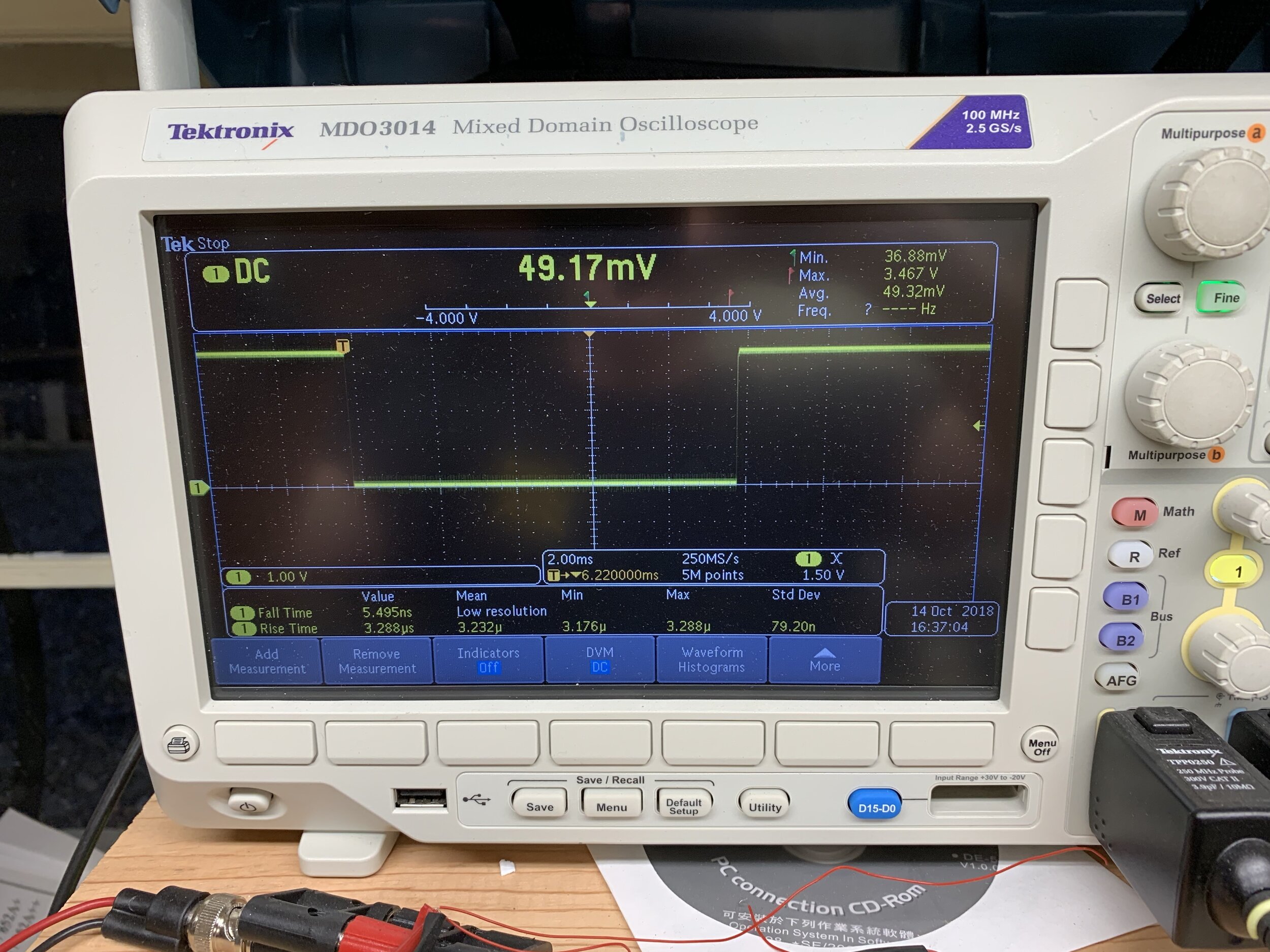 Sure enough, I get a really nice "press" of the shutter button from the Arduino! :-D